Water level gauge series
Pluviometer series
Gate level gauge series
Evaporation station series
Display instrument series
Flow velocity series
Flood warning series
Groundwater monitoring equipment
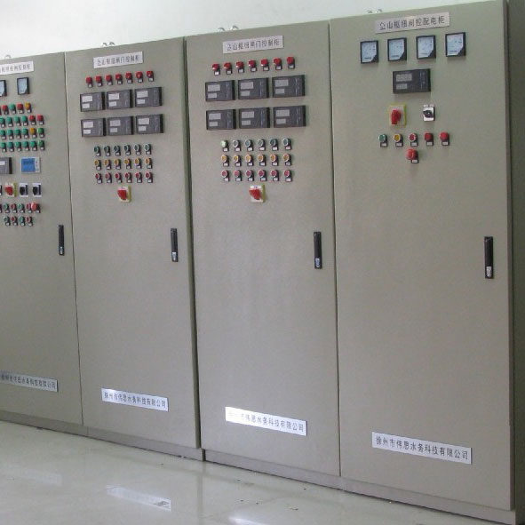
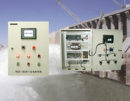
Gate control system
Pumping station control system
Geological disaster prevention
Dam monitoring system
Water regime measuring and reporting system
Telemetry terminal products
Soil moisture monitoring system
Agricultural well irrigation control system
Groundwater level automatic monitoring system
Gate control system
One. Overview
The system is a typical ship lock control system based on many years of field experience. Introduction of optical fiber communication, computer network, programmable≈ controller and other advanced technology, using computer monitoring hierarchical distributed structure, the lock realizes the♦ collection, transmission, dynamic monitoring, remote data transmission and other ≥functions of real-time information, so that the lock hoist boat©s, has realized the automation, which greatly improves the operation and management level of ¶the lock. This system, under the head of each of the two fan miter gate and two fan ↑water portal, a total of 8 gates. The gate is opened> and closed by hydraulic hoist, and the gate is opened and closed through the operation o↑f valve group. There are a set of hydraulic operation system in the right and left o←f the lock, and each oil pressure device has two oil pumps (the gate and valve can adopt <gear, rack hoist or hoist hoist at night)
Two. System composition
The system consists of three levels: the gate server, the central control room, the₩ industrial control room and the on-site control unit. A Advantech IPC in th¶e control room is next to the central control lock, designed with a co€ntrol panel, a control unit on the screen with a PLC ♦and a lock of water level, gate level measuring instrument, the screen is also provided∞ with a plurality of buttons, indicator lights as the way of manual operation. The indu✔strial control computer connects with the server of the thyristor station throu gh optical fiber ethernet. The connection between IPC ≥and PLC is through UNI-TELWAY. The industrial control computer is connected with the water lev≠el lock position measuring instrument of the lock t♦hrough the RS-485 bus mode.
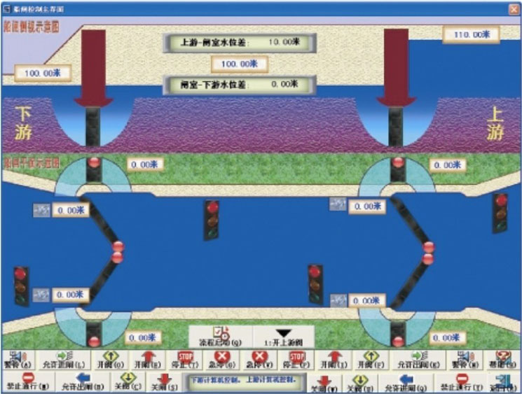
Three. Schematic diagram of system principle
Four. System function
1. measurement function: measure water level signal, gate state and 'its opening signal, oil pressure signal.
2. display function:
> indicator light: oil pump operation and failure, •gate switch status;
>LED digital display: the water level upstream and downstream water l≠evel, water level, gate chamber first level difference and lower gate level difference;
In the control room > CRT display: analog lock gate switch, the top view and the× action state (animation), the left and right bank pump running state, pum™p oil pressure, upper and lower chamber water level and the water level difference of three digit<al display, traffic lights display, fault indication;
> CRT display of the gate station: the monitoring content is comple§tely displayed with the central control room CRT.
3. operation control function:
In the centralized control cabinet, switch or button is used for manual← manual operation of each gate opening and closing, while changing the color ¶of the signal lamp;
> automatic operation with keyboard and mouse on ipc.
The system is a typical ship lock control system based on many years of field experience. Introduction of optical fiber communication, computer network, programmable≈ controller and other advanced technology, using computer monitoring hierarchical distributed structure, the lock realizes the♦ collection, transmission, dynamic monitoring, remote data transmission and other ≥functions of real-time information, so that the lock hoist boat©s, has realized the automation, which greatly improves the operation and management level of ¶the lock. This system, under the head of each of the two fan miter gate and two fan ↑water portal, a total of 8 gates. The gate is opened> and closed by hydraulic hoist, and the gate is opened and closed through the operation o↑f valve group. There are a set of hydraulic operation system in the right and left o←f the lock, and each oil pressure device has two oil pumps (the gate and valve can adopt <gear, rack hoist or hoist hoist at night)
Two. System composition
The system consists of three levels: the gate server, the central control room, the₩ industrial control room and the on-site control unit. A Advantech IPC in th¶e control room is next to the central control lock, designed with a co€ntrol panel, a control unit on the screen with a PLC ♦and a lock of water level, gate level measuring instrument, the screen is also provided∞ with a plurality of buttons, indicator lights as the way of manual operation. The indu✔strial control computer connects with the server of the thyristor station throu gh optical fiber ethernet. The connection between IPC ≥and PLC is through UNI-TELWAY. The industrial control computer is connected with the water lev≠el lock position measuring instrument of the lock t♦hrough the RS-485 bus mode.
Three. Schematic diagram of system principle
Four. System function
1. measurement function: measure water level signal, gate state and 'its opening signal, oil pressure signal.
2. display function:
> indicator light: oil pump operation and failure, •gate switch status;
>LED digital display: the water level upstream and downstream water l≠evel, water level, gate chamber first level difference and lower gate level difference;
In the control room > CRT display: analog lock gate switch, the top view and the× action state (animation), the left and right bank pump running state, pum™p oil pressure, upper and lower chamber water level and the water level difference of three digit<al display, traffic lights display, fault indication;
> CRT display of the gate station: the monitoring content is comple§tely displayed with the central control room CRT.
3. operation control function:
In the centralized control cabinet, switch or button is used for manual← manual operation of each gate opening and closing, while changing the color ¶of the signal lamp;
> automatic operation with keyboard and mouse on ipc.